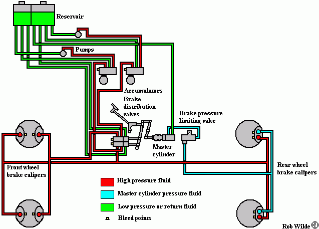
The hydraulic system: |
|
|
|
The brake system: |
|
|
|
Introduction of the brake system
 The components of the brake system
The components of the brake system are demonstrated with a part of the diagram for the chassisnumbers 7404 to 22072.
Top left we see the reservoir, the two pumps and the accumulators. Bottom left we see the two front wheel brake calipers. On the right of them below the brake pedal we find the two brake distribution valves; they work like a kind of tap that lets through the high pressure liquid to the brake calipers. On the right of these valves the master cylinder is drawn. It gets its hydraulic liquid from the reservoir and can be called a low pressure circuit. between the master cylinder and the rear brake calipers a brake pressure limiting valve is mounted. It prevents the brakes from locking up during am emergency stop. Finally bottom right we see the rear wheel brake calipers.
An overall picture of all components and their connections can be seen on page Conjunction of components.
|
 Marinus Rijkers. Disclaimer
 Marinus Rijkers. Disclaimer