The hydraulic system: |
|
|
|
The brake system: |
|
|
|
The Master cylinder
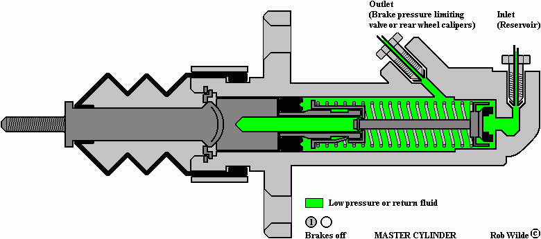
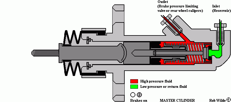
In the next master cylinder two drawings illustrate the working of the accumulator.
For a view on each separate drawing you can go to the bottom of this page.
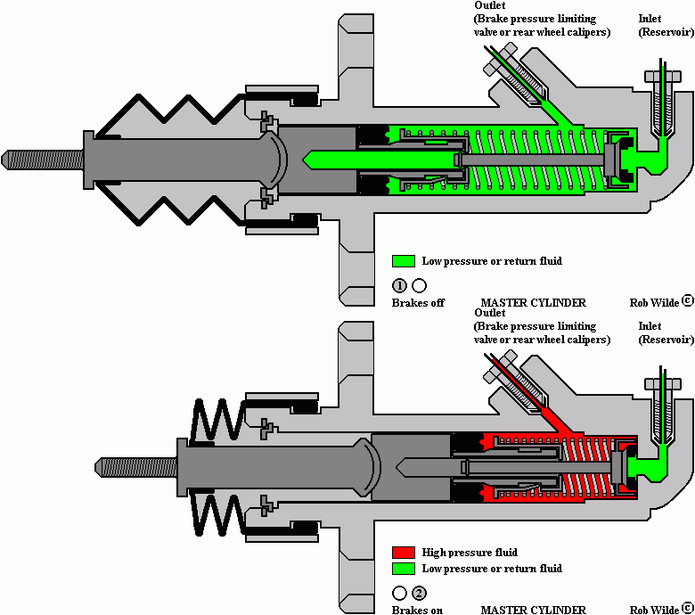
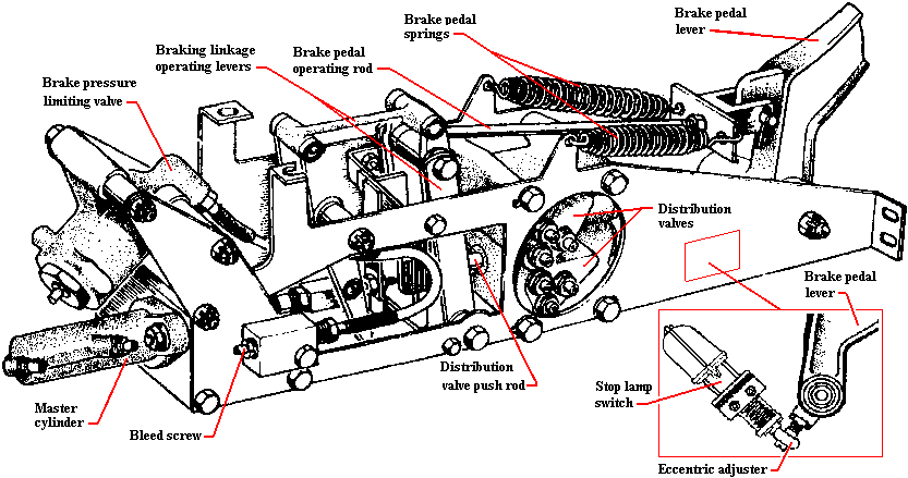
All cars made before chassis number 22118 are fitted with a master cylinder in the brake circuit. The master cylinder is directly connected to the reservoir. When the hydraulic pressure will decrease the master cylinder will provide a small amount of brake power. When the brake pedal is released the plunger sucks in hydraulic fluid. When the brake pedal is operated the fluid is pressed through a one way valve. In this case pressure increases, causing the lower brake pistons of the rear calipers to be activated. This system must be seen as a last possibility to stop the car. The brake power of the master cylinder is not sufficient enough to slowing the car down in normal driving conditions. The master cylinder is mounted in the brake actuation box.
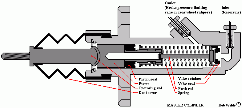
The next drawing shows the master cylinder when watching them from the bottom beneath the driver's chair:
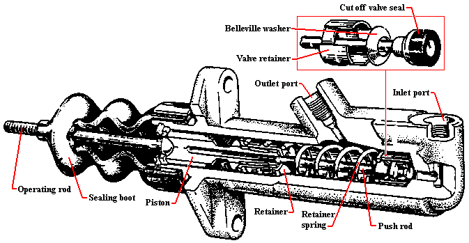
The master cylinder is part of the brake actuation box:
The animated drawing at the top of this page is built-up with the next drawings.
|
 Marinus Rijkers. Disclaimer
 Marinus Rijkers. Disclaimer