The hydraulic system: |
|
|
|
The brake system: |
|
|
|
The Brake distribution valve
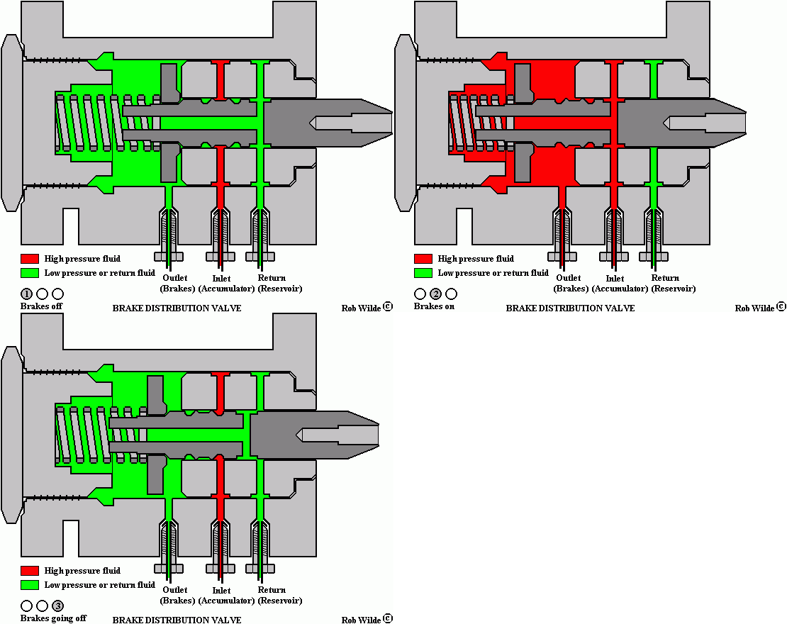
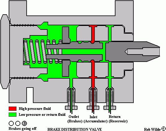
In the next animation three drawings illustrate the working of the accumulator.
For a view on each separate drawing you can go to the bottom of this page.
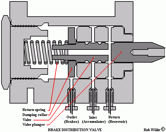
The next drawing shows the brake distribution valve again but now provided with some explanations:
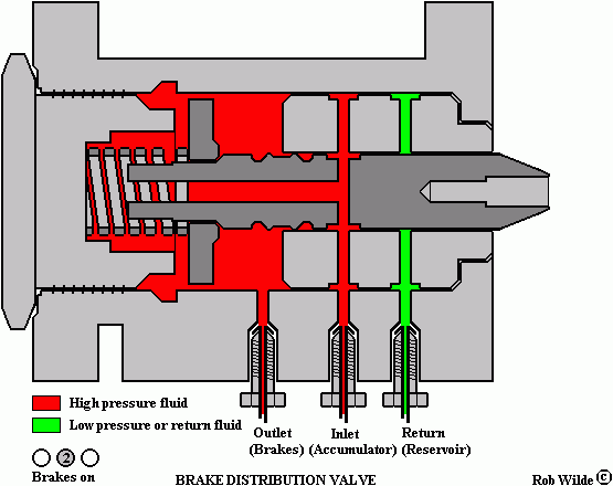
 When the brake pedal is operated the plungers of the two brake pressure distribution valves are pushed in. Several openings in the valve lead the pressurised hydraulic fluid to the brake pistons.
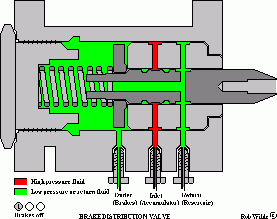
When the brake pedal is not operated the return pipe is opened and the fluid flows back to the reservoir. The distribution valves function like taps.
The counter pressure that can be felt when operating the brake pedal is caused by the master cylinder. On the later models (from chassisnumber 22073) the master cylinder was omitted and the counter pressure was caused by a rubber. A benefit of this system is that the metering of the braking was easier to determine.
The brake distribution valves are located in the brake actuation box. This box also contains the master cylinder and the brake pressurelimiting valve. The box is mounted below the brake pedal below the car and is covered with an aluminium sheet to protect them from dirt. The page about the master cylinder shows a drawing of this brake actuation box.
|
A cut-away drawing of the brake distribution valve (left) and a drawing of the valve when watching the bottom of the car:
The animated drawing at the top of this page is built-up with the next drawings.
|
 Marinus Rijkers. Disclaimer
 Marinus Rijkers. Disclaimer