The hydraulic system: |
|
|
|
The fluid pressure control: |
|
|
|
The hydraulic pumps
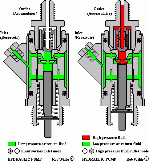
In the next animation two drawings illustrate the working of the hydraulic pumps.
For a view on each separate drawing you can go to the bottom of this page.
The next drawing shows the pumps again but now provided with some explanations:
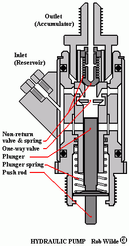
Two pumps, fitted on the top of the engine, pressurise the hydraulic fluid. They are driven by the camshaft of the engine. The fluid from the reservoir is sucked in by a valve activated by a push rod. The one way valve, which is fitted in the upper part of the pump body, prevents the fluid from floating back. The pressurised hydraulic fluid floats to the accumulators.
|
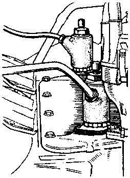
The next drawing shows the hydraulic pumps when watching them from the top of the engine:
Some cut-away drawings of the pumps:
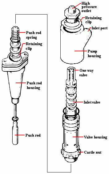
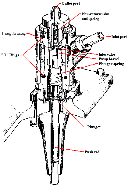
The animated drawing at the top of this page is built-up with the next drawings.
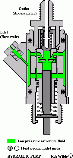
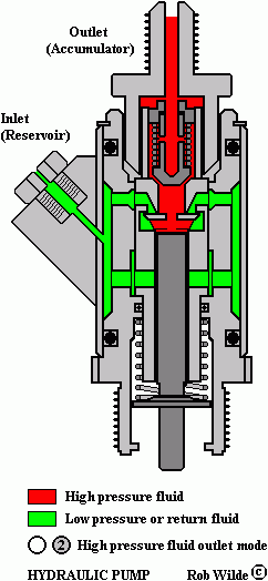
|
 Marinus Rijkers. Disclaimer


