Like any other automatic gearbox, the GM400 is based on planetary gears. The GM400 has two planetary gears. Planetary gears have a center gear and multiple satellite gears. These are held together by a carrier, positioned in a drum with teeth on the inside. The construction is compact, very strong and can be constructed to give multi-ratio gears. A planetary gear is operated by a slip band that can lock-up the drum, stopping it from rotating. Several clutches are able to secure the carrier to the drum, or to connect the carrier to the secondary planetary gear. Every combination gives a different output gear ratio, a revers rotation of the output shaft inclusive. The GM400 has three forward gear ratios and one reverse ratio. Forward gear ratios are 2.5:1 (1st gear), 1.5:1 (2nd gear) and 1.0:1 (3rd gear). The reverse gear ratio is 2.07:1.
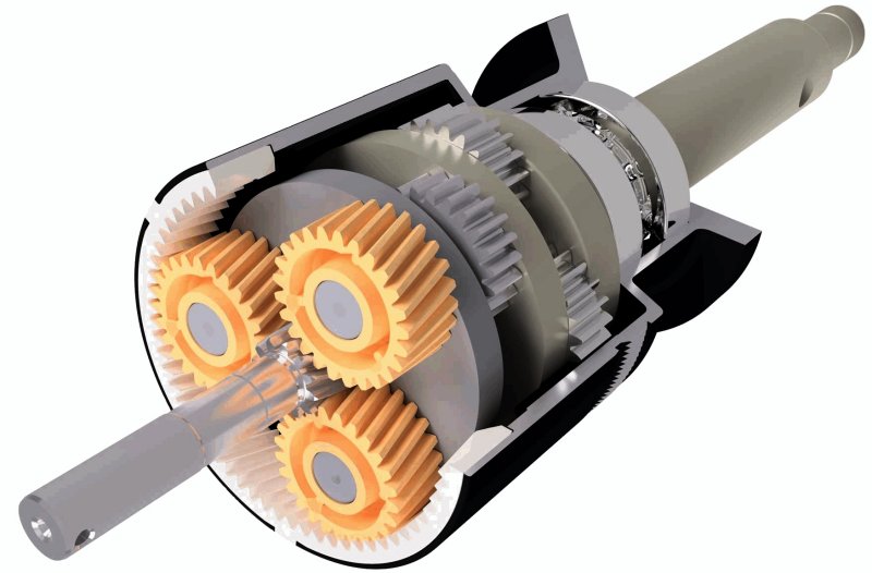
Example of a planetary gear, main component of every automatic gearbox.
The next drawing shows the main mechanical parts of a GM400 with fixed turbine blades (1967 onwards). The torque convertor (left, green) acts like an 'automatic coupling' between the crankcase of the engine and the input shaft of the gearbox. The centre section of the convertor (light green) is connected to the outer input shaft and operates the gearbox fluid pump (purple, front part). The turbine of the torque convertor (dark green) is connected to the inner ingoing shaft. That shaft is connected to the first drum (red) that contains hydraulic couplings (purple, centre part). Further backwards (to the right in the drawing), the first and second planetary gears (blue) are visible. The slip bands (green) are wrapped around the drums. The speedometer drive (purple, rear part) is propelled by the output shaft (yellow). At the bottom, right, the gear shift lever is shown (yellow) and the fluid oil pan that contains the fluid filter. An electrical connector is fitted to activate the kick-down detent solenoid. The external electrical motor (the 'actuator') is a Rolls-Royce and Bentley feature. In the actuator an electrical switch, that is connected to the gear lever, controls the shifting of the gearbox to the desired position.
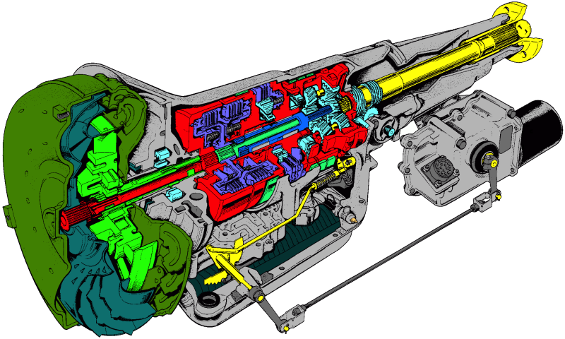
Inside view of the GM400.
In the following picture the hydraulic/mechanical parts are shown, such as the hydraulic clutches and servos. The servos are connected to the front and rear slip-bands. The 'sprag' in the drawing is a large washer with several teeth that is part of a clutch. The purpose of the 'flex-plate' is to eliminate vibrations and is mounted to a flywheel. The flywheel is connected to the crankshaft of the engine.
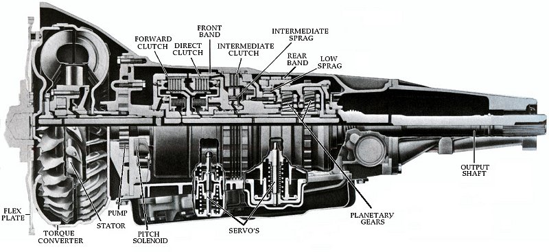
The mechanical/hydraulic components.
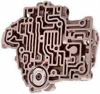
The hydraulic/mechanical parts are controlled by valves that are operated by hydraulic pressure and/or springs. The main hydraulic pressure is produced by the internal hydraulic pump. The valves are incorporated in a valve regulator box. Variable fluid pressure is regulated by the speed governor, by torque demand, the position of the gear lever, the kick-down switch and the vacuum modulator. If hydraulic pressure rises or lowers to overcome the force of a valve spring, the valve opens or closes, and controls the clutches and/or servos. A specific combination of activated or de-activated clutches and servos determines which gear will be selected.
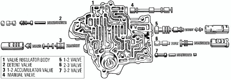
The valve regulator box.
|
 Marinus Rijkers. Disclaimer
