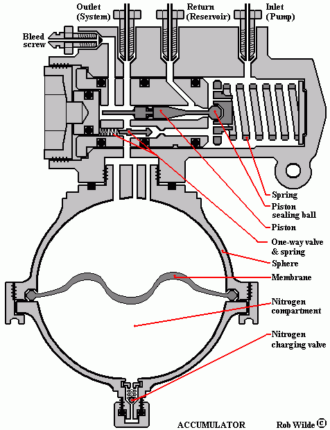
The accumulators are the safety belts of the hydraulic system. If in any case the engine stops while the car is still driving the accumulators will keep the hydraulic pressure at the normal operating level. In this situation the brake system remains in full operation.
The pressure of the hydraulic fluid is kept by means of a sphere which is divided by a diaphragm. The lower compartment of the sphere is filled with pressurised nitrogen. The pressure of the nitrogen is about 70.0 kg/sq.cm. Ones the pumps are activated by starting the engine, the hydraulic fluid pressure will increase slowly until it reaches 175.0 kg/sq.cm. This pressure will open the return valve. The fluid will now float back to the reservoir protecting the sphere from overcharging. In normal conditions the pressure of the hydraulic fluid will remain 168, 0 kg/sq.cm. Ones the engine is stopped the pressure in the sphere will be sufficient enough to operate the brakes for about 50 times which will allow the driver to stop the car in normal conditions. The driver will be warned whenever the pressure in the spheres will decrease to alarming levels. A pressure sensor, which is mounted on each of the accumulator valve bodies, will be activated at this time. The sensors are connected to the warning lights, mounted on the facia panel. If the car is stored for some time the pressure will slowly decrease. The warning lights will be activated immediately when the starter key is turned in the first position. If the engine runs the lights must go out at once. The warning lights can be tested by pushing the test button on the facia. If the fluid pressure decreases immediately after the engine is stopped probably one or both diaphragms are leaking. This will allow the nitrogen to mix with the hydraulic fluid causing the discharge of the sphere. Before any work is done on the hydraulic system the accumulators must be discharged by activating the brake pedal for about 50 times or by bleeding the accumulator.
|
 Marinus Rijkers. Disclaimer
 Marinus Rijkers. Disclaimer