The hydraulic system: |
|
|
|
The hydraulic diagrams: |
|
|
|
Introduction of the diagrams

Build-up of the diagrams
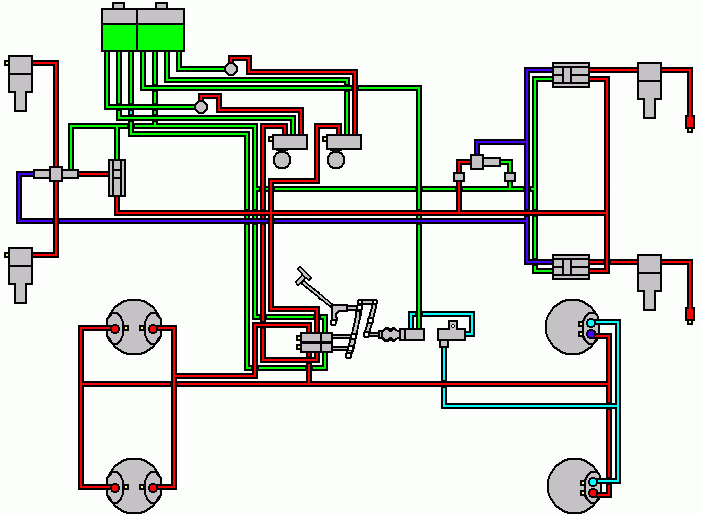
The diagrams consist of a solid composition. In the centre of the upper part of the drawing the components are drawn that control the fluid pressure. On the left and right top you see the components that control the height of the car, on the left the front height control, on the right the rear height control.
In the centre of the lower part of the drawing you see the components that deal with the braking, on the left the brakes of the front wheels, on the right the brakes on the rear wheels.
So when we draw an imaginary horizontal line through the middle of the diagram, we see the height control system on the left and on the right of the upper part and we see the the brake system on the left and right of the lower part.
Three hydraulic circuits
The Silver Shadows has a hydraulic system that contains 3 circuits.
Circuit 1 consists of the front part of the reservoir, the front pump, the front accumulator (at the Silver Shadow II the left accumulator) and one of the two distribution valves that regulates the front brake calipers of the front wheels.
Circuit 2 consists of the rear part of the reservoir, the rear pump, the rear accumulator (at the Silver Shadow II the right accumulator) and again one of the distribution valves; this distribution valve regulates the rear brake calipers of the front wheels and via the restriction valve the front calipers of the rear wheels. Also the height control system is included in this circuit.
Circuit 3 consists of the master cylinder that also gets its fluid from the rear part of the reservoir. The circuit of the master cylinder was deleted on the Silver Shadow II.
What was changed on the hydraulic system
In the past many changes were put through in the system. The diagrams tell us what has been changed.
The first changes were carried through already after a few months after launching the Silver Shadow. From chassisnumber 1755 the ram valves of the height control system were changed. You can see that in the second diagram.
Again a few months later the second modification was carried through. The working of the brake pressure limiting valve was changed. You can see that in the third diagram.
It lasted until 1969 before the third modification was carreid through. From chassisnumber 7404 the height control system on the front wheels was deleted. This part is missing in the fourth diagram.
The last important modification was carried through in 1975 on chassisnumber 22073 and was the last until production of the Silver Shadow II ceased. The modification concerned the deletion of the master cylinder. Have a look at the fifth diagram.
The fluid pressure control
The fluid pressure system consists of three components, namely the brake fluid container (Reservoir), the high pressure Pumps and the Accumulators. In the left upper part of the diagram the reservoir is drawn. The pumps are positioned on the right of it. Right below of the pumps you see the accumulators. The fluid that is suctioned from the reservoir is brought to pressure by the pumps and put to the accumulators.
The accumulators hold the fluid under pressure when the engine doesn't run any more while driving and the pumps have stopped functioning. In that case the brake pedal can still be used some 50 times. The car can safely be stopped in all circumstances even when the engine has ceased to run for one reason or another. The average pressure in the system is about 150 atmosphere.
The system may only be filled with Castrol RR363 hydraulic fluid. This fluid takes care of the lubrication of the pumps. After chassis number 50001 the hydraulic fluid is replaced by mineral oil. These late systems can be recognized by green labels that are placed on top of the reservoir and on most of the hydraulic system components. The two different types of fluid may never be mixed or replaced by one another.
|
 Marinus Rijkers. Disclaimer
 Marinus Rijkers. Disclaimer